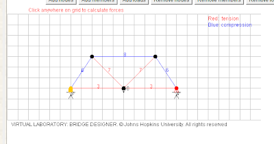
Truss bridge being used in calculations
The figure above shows the calculations neccessary to obtain all of the forces on the truss. They are place into an Excel doc for easy accessibility
2) Truss analysis results
Note that the forces are equally and evenly spread across the bridge
4) In order for the forces on Bridge Designer to match the forces from the method of joints, one must correctly scale the bridges to the same size. If either bridge is longer or shorter than the pther in any way, the results are not going to be the same, because they are simply different bridges
5)
Once again, if this bridge in Bridge Designer is scaled exactly the same as out Knex bridge, the forces on each of the members should be near equal. If the design has been sone correctly, the forces from one side should be symmetrically equal to the forces on the opposite side. While this is usually true, something must have happened when creating this bridge in Bridge Designer, because it continues to show a force of zero on one section of the bridge, which cannot be possible while under a load from the center of the bridge.


No comments:
Post a Comment