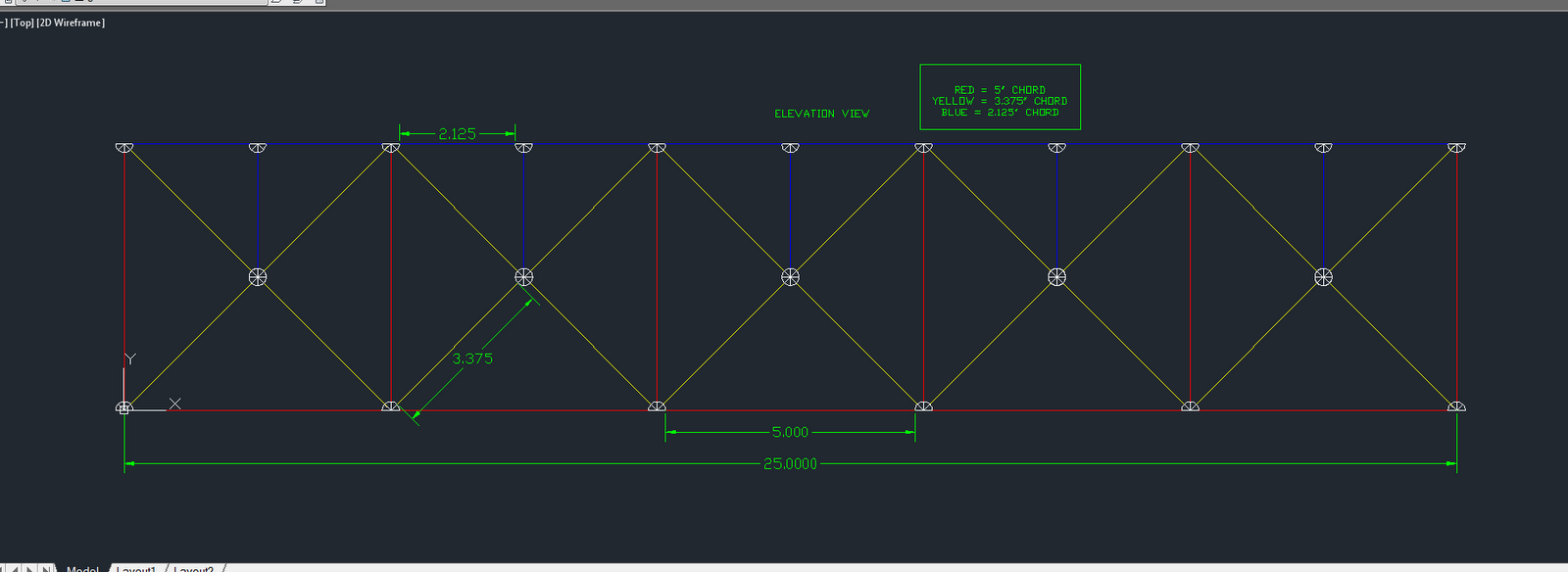
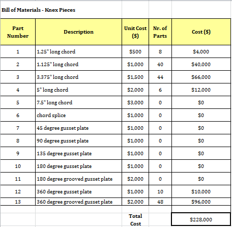
The goal for the KNEX bridge structure is to have the best cost/breaking load ratio. For this design each individual had to create a sketch of a truss design for a bridge 2ft long. This bridge design is is a square shape with triangle webs connecting in an x shape. There is then a vertical brace connecting the center of the x to the top cord. This should help distribute the weight of the load test evenly over the bridge and mostly at the strong points of the bridge. Inside the bridge are cross members that will keep the bridge from collapsing from side to side.
Elevation View:
Plane View:
Truss Bill of Materials:
The shape of the bridge was not altered during the process of drawing and designing the bridge. The original idea and design was used. It is similar to the WPBD bridge that I designed. Since this bridge was the lowest cost in the class I figured it would be a great starting point. The hardest part about the KNEX design was getting the pieces to work the way I wanted them to. The angle increments make it hard to follow a specific design unless it can be turned into all 45degree increment angles.
This assignment demonstrated the importance of visualization and the need to work out ideas on paper before testing them. This drawing will also give a starting position to work off of once the first load test is ran. There are unexpected difficulties with the angle increments and the length of the bridge. It is very hard to create a bridge that is actually 2ft long.
Tuesday, May 1, 2012
Week4-WPBD vs. KNEX
Over the past few weeks the group has used WPBD to create truss structures and to analyze how loads affect a bridge. This was a great tool to see how trusses are affected by weight and how to design them to withstand the weight. For the second half of the term the group will be using KNEX to build sample bridge truss structures to physically test. The KNEX has an advantage over the WPBD because it is a real life simulation. It also allows for the builder to involve cross members from side to side rather than just the elevation of the truss. These cross members will be crucial in the weight test to keep the bridge from collapsing from side to side. One disadvantage to the KNEX is that they can only be connected in 45degree increments.
Last week the group concentrated on finding out what KNEX pieces were the strongest. The group also tried different designs to find out what kind of limitations there are for the KNEX pieces. The 45degree increments for connections limit some of the truss designs. It will take a good bit of time studying truss systems and testing them to create a bridge with the lowest cost/breaking load ratio.
Week 4: WPBD vs Knex
Through the first half of this term, we were given the opportunity to utilize the West Point Bridge Designer program to learn about truss bridges and how they work. This was a great interactive tool for designing our first sets of truss bridges. but now its time to move on to bigger and better things, and that being Knex. For the 2nd half of the term we will be physically building our own truss bridges and seeing how they hold up to a large load. This is where Knex overrides WPBD, because no computer program can give one a better experience than actually doing it in the real world. Building these Knex bridges allows us on a very small scale to experience first-hand how a truss bridge handles a load, rather than clicking a button and waiting for a result on a computer screen.
Our group spend a large amount of lab time last week becoming as familiar as possible with the Knex pieces. We wanted do our best to find out what exactly can and cant be done with them. We felt that this approach would be the most helpful to us for completing our designs in the upcoming weeks. out of class our time was mainly focused on creating our first Knex design plans for this upcoming weeks lab. That way, we are all ready to go with beginning our builds.
A2: Fitzpatrick
1) The major design goal for this bridge was to sketch the most cost effective yet structurally safe bridge possible. After performing some experimentation, it seems as if a square bridge with triangle crossmembers is the best way to go. Additionally, some small vertical crossmembers on the upper triangles in the bridge were added to help increase strength.
2) Plan View
3) Elevated View
4) Front View
5) Truss Build of Materials
6) The design of this bridge did not change very much once the structural shape was decided. Many different ideas came about at first, but once this design started to take shape, there wasnt much looking back. The most difficult part during this bridge design was adhering to the limited list of pieces allowed to use. Many designs were just not possible because of a lack of chords of a certain length, therefore limiting the possiblility of a wide variety in the design.
7) This design project showed that one has to learn to "work with what they have" in certain situations rather that just designing anything. Needing to build a bridge with only 5 different length chords proved to be a challenge similar to one of the real world. The ability to succeed in situations like this is a vital skill that will turn out to be critical in the future.
2) Plan View
3) Elevated View
4) Front View
5) Truss Build of Materials
6) The design of this bridge did not change very much once the structural shape was decided. Many different ideas came about at first, but once this design started to take shape, there wasnt much looking back. The most difficult part during this bridge design was adhering to the limited list of pieces allowed to use. Many designs were just not possible because of a lack of chords of a certain length, therefore limiting the possiblility of a wide variety in the design.
7) This design project showed that one has to learn to "work with what they have" in certain situations rather that just designing anything. Needing to build a bridge with only 5 different length chords proved to be a challenge similar to one of the real world. The ability to succeed in situations like this is a vital skill that will turn out to be critical in the future.
Wednesday, April 25, 2012
A2- Parker
1. The design goals for this particular bridge are to create a bridge that has the best price to weight ratio. The bridge is a square shape with triangle reinforcements in order to create a design that is visually appealing and to allow for web members to be added in such a way that allows the load to be distributed evenly across the bridge.
2. Elevation View
3. Plan View
4. Truss Bill of Materials
5. The shape of the bridge was not changed much during the design, the hardest thing encountered was meeting the length requirement, many of the designs created were only 22" in length not the required 24". This led to problems when trying to find a design where the angles would work yet the length was sufficient. This design is certainly not the best work but without sitting in a lab and testing different designs there is no way take this bridge to the next level.
6. This assignment has shown that when working on designing something you need to have an image of what you want the design to look like going in so that you have something to work off of yet at the same time you need to keep an open mind in case problems arise. In this design problems arose that were unexpected such as trying to create a bridge that was long enough to span a 24" opening yet at the same time keeping in mind the fact that all connections must be made in increments of 45 degrees.
2. Elevation View
3. Plan View
4. Truss Bill of Materials
5. The shape of the bridge was not changed much during the design, the hardest thing encountered was meeting the length requirement, many of the designs created were only 22" in length not the required 24". This led to problems when trying to find a design where the angles would work yet the length was sufficient. This design is certainly not the best work but without sitting in a lab and testing different designs there is no way take this bridge to the next level.
6. This assignment has shown that when working on designing something you need to have an image of what you want the design to look like going in so that you have something to work off of yet at the same time you need to keep an open mind in case problems arise. In this design problems arose that were unexpected such as trying to create a bridge that was long enough to span a 24" opening yet at the same time keeping in mind the fact that all connections must be made in increments of 45 degrees.
Week 4: KNEX vs WPBD
Last week we
focused our efforts on working with West Point Bridge Designer to experiment
with different designs and properties of bridges, prior to lab this week it was
essential to have begun thinking about designs for our prototype bridges. This
coming week we have agreed to draw our designs for bridge and to start thinking
about what designs or design components we should implement into our team bridge
in the coming weeks. This week we had not real major accomplishments, due to the
fact that our time spent in the lab was spent testing our ideas with knex to
enhance our understanding when we design our bridges. The group nor myself see
any problems on the horizon.
The
similarities between West Point Bridge Designer and Knex are that each piece
has a price associated with it and each piece has a load that it can carry.
Designs created in West Point Bridge Designer can theoretically be transferred
and built using Knex, with only minor changes conforming to
The difference
between the two systems is that in West Point Bridge Designer, the beams can be
attached to the gusset plates at any angle whereas with KNEX we are limited to attaching
beams to the gusset plates at 45 degree increments. Furthermore with Knex we
only have one type of material that we have to choose from whereas in West
Point Bridge Designer the material can be changed and with this the properties
of the materials change. Another advantage to KNEX is the fact that they are
something that we can hold and assemble allowing us the opportunity go get real
life design experience, it is one thing to see a drawing of a bridge and manipulate
it and it is a totally different thing to assemble a bridge and analyze the
failure. In addition with KNEX the bridge is exposed to more environmental factors
that have an impact on design than West Point Bridge Designer is capable of
showing.
Tuesday, April 24, 2012
Week 3: WPBD
This last week in engineering the group sat down together to analyze our west point bridge design bridges. The group decided to use the bridge I created as the lowest cost. In the next weeks we will need to take truss designs from what we have learned and use them to create a KNEX truss system. Our group was in the top 3 for the lowest bridge cost which is really good. The entire group is focusing well on our goals and striving to do the best possible. Hopefully we can put the same effort into the KNEX project.
West Point Bridge Design is a program that can be used by Civil Engineers to get a general idea of how truss systems work on bridges. It is also user friendly for people who do not know anything about bridges. The WPBD program does a good job at simulating the stress applied to a bridge by the dead load and a live load driving over it. It is able to calculate accurate costs for a bridge and it helps the user to see the amount of force on individual members of a truss system. The problem with WPBD is that it does not take any consideration into the trusses that run from side to side across the bridge. This doesn't allow us to see how weight can affect the bridge from side to side or how wind would affect it. Due to this WPBD is not very realistic when compared to real life bridges.
Subscribe to:
Posts (Atom)