Tuesday, May 29, 2012
Week 8: Bridge Process
In the past week our group has been working on building the best 3' span bridge possible. We have experimented with many different design options and we think we have found one that will perform satisfactorily. In our week 9 lab we will test this bridge to see the results of our efforts. Through designinf these bridges I have learned that the bridge design process is not as simple as throwing together a structure and seeing if it holds up. I have learned about the different loads that a bridge faces over the course of its life such as compression forces and tension forces resulting from the load, and also lateral forces caused by elements such as wind. Some of the main things that i have learned though is that the one smallest issue with a bridge can cause catastropic failure. Bridge designers learn from these failures though. While hopefully these failures do not occur on a full scale active bridge, the use of breaking scaled down bridges is the best way to learn about how to improve them.

Wednesday, May 23, 2012
Week 8 Bridge Process
This past week we have worked to complete a
bridge designed to span a 36” opening, and worked to determine ways that our bridge
could be improved using the analysis tools we have at our disposal. This coming
week we will work to further improve our design to have the best possible
bridge ready to test in week 9. Overall I would say that we had no major accomplishments
this past week. As a team the only issues that we faced were disagreements on
how to improve our bridge and prevent it from racking.
Throughout the term, each week brought something
new to the table and something that I had not seen before. We started out using
modeling programs that helped us to learn to maximize the tension and compression
forces that a gusset plate feels. In maximizing the forces that the gusset
plate feels you are able to use the smallest size members possible, in many
cases this lowers the total cost of the design.
In looking back at the videos the bridge failures shown in class it is clear
that a bridge designer plays an important role in keeping people safe, if even
one small aspect of the bridge has a flaw it can lead to a catastrophic failure
and significant loss of life. I have also learned that when designing a bridge
that is most efficient, that the bridge should be able to handle a load that
will change over time; just as we have seem with local bridges the weight of paint
is added on as the years go by and our vehicles continue to increase in size as
a result increasing the load that the bridge must carry. Bridges are subject to
more forces than meet the eye, there is the typical gravitational force but
what many people don’t realize is the tension and compression in each member as
well as the overall impact of the elements and external factors on the bridge.
Tuesday, May 22, 2012
A3: Fitzpatrick
1) Calculations of forces in the truss members using the Method of Joints


3) Truss analysis via Bridge Designer
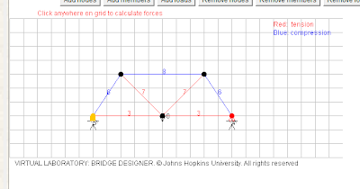

6) The method of joints analysis is a good way to maually determine an idea for a load capacity for a bridge. breaking the desgin down into single specific pieces gives one a better chance at not making a mistake. One of the most vital things we can do to assure a better bridge is to use gusset plates with at least 3 joints on them. These joints are stronger than all the others when it comes to the load testing. While these are more epensive than other joints, they are well worth it in the long run. This program is help when it comes to doing this.

Truss bridge being used in calculations

The figure above shows the calculations neccessary to obtain all of the forces on the truss. They are place into an Excel doc for easy accessibility
2) Truss analysis results

Note that the forces are equally and evenly spread across the bridge

4) In order for the forces on Bridge Designer to match the forces from the method of joints, one must correctly scale the bridges to the same size. If either bridge is longer or shorter than the pther in any way, the results are not going to be the same, because they are simply different bridges
5)

Once again, if this bridge in Bridge Designer is scaled exactly the same as out Knex bridge, the forces on each of the members should be near equal. If the design has been sone correctly, the forces from one side should be symmetrically equal to the forces on the opposite side. While this is usually true, something must have happened when creating this bridge in Bridge Designer, because it continues to show a force of zero on one section of the bridge, which cannot be possible while under a load from the center of the bridge.
A3: Miller
1) Calculations of forces for the truss members using the Method of Joints.
 Truss Bridge used for the Method of Joints
 This shot shows the calculations done in excel to determine the forces on each member.
2) Results of Analysis
Forces Acting on Each Member
 Members symmetrical to one another have the tension and compression force acting upon them.
3) Replication of Bridge Analysis done in Bridge Designer

4) In order for the hand analysis to show the same results as the Bridge Designer calculations the bridge must be scaled to the same size. In Bridge Designer each individual square is 2"x2". The drawing that I did in the Bridge Designer does not have the same lengths as the hand drawn one I did the calculations for. It does however have very similar results.
5)
 The forces in the KNEX bridge will be fairly similar to the forces calculated by the bridge designer analysis. The member lengths are a little different and there are less sections than the real bridge. The forces felt by the 2 middle sections should be relatively realistic when compared to the KNEX bridge. The 2 outside sections are showing unrealistic numbers. While this is not the full bridge formation it should give us the general idea we need to help improve our bridge design.
6) Using the method of joints analysis allows the determination of tension and compression on individual members of a bridge for a given load. Using this information it is possible to apply the KNEX connection strenghts to determine a failing load for the bridge. The connectors with 3 members attached to them have the highest pull out force at an average of 35.6lbs. Connectors with only 2 members attached suffer almost a 10lbs. decrease in strength which leaves them at 26.5lbs. The weakest attachment to a connector is 1 member. The pull out force for this is 20.7lbs. With this data it is obvious that connectors should be loaded with at least 3 members to assure the highest pull out force. There is also a possibility to determine pieces that are not giving the bridge any structural support by analyzing the results of calculations and using the pull out test information. These pieces can be removed to decrease cost.

2) Results of Analysis
Forces Acting on Each Member

3) Replication of Bridge Analysis done in Bridge Designer

4) In order for the hand analysis to show the same results as the Bridge Designer calculations the bridge must be scaled to the same size. In Bridge Designer each individual square is 2"x2". The drawing that I did in the Bridge Designer does not have the same lengths as the hand drawn one I did the calculations for. It does however have very similar results.
5)

6) Using the method of joints analysis allows the determination of tension and compression on individual members of a bridge for a given load. Using this information it is possible to apply the KNEX connection strenghts to determine a failing load for the bridge. The connectors with 3 members attached to them have the highest pull out force at an average of 35.6lbs. Connectors with only 2 members attached suffer almost a 10lbs. decrease in strength which leaves them at 26.5lbs. The weakest attachment to a connector is 1 member. The pull out force for this is 20.7lbs. With this data it is obvious that connectors should be loaded with at least 3 members to assure the highest pull out force. There is also a possibility to determine pieces that are not giving the bridge any structural support by analyzing the results of calculations and using the pull out test information. These pieces can be removed to decrease cost.
A3- Parker
1) Calculations of forces in the truss members using the Method of Joints.
 |
| Truss Bridge That was used in Method of Joints |
 |
| This image shows the calculations that were made to determine the forces on each member, these formulas were derived by hand when solving the truss and were imputed into Excel so that hand calculations are not necessary as the bridge constraints change. |
2) Results of the Analysis above
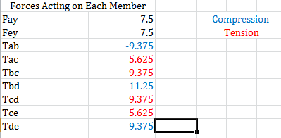
As you can see above members symmetrical to one another have the tension or compression force acting upon them
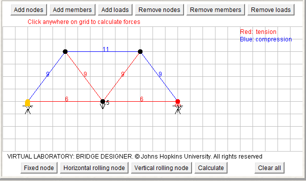
4) In order for the hand analysis to correspond to the analysis compiled by Bridge Designer one must scale their bridge so that the forces correspond with the values calculated by Bridge Designer. In the drawing above, each block represents 2" in length, and the nodes correspond to the connecters on the hand drawn bridge so the bridge in the image corresponds to the bridge that the analysis was preformed on, not surprisingly the results of the two analysis's are similar.
5)
 The forces in the knex bridge should be similar to the forces in the bridge designer analysis. The member lengths are similar therefor the forces felt should the similar for the center two sections. the forces shown in the diagram for the sections on the outer sides of the diagram are showing non-realistic forces. The bridge design above while not a full bridge, provides a glimpse at the final product, a bridge constructed using the same sections as shown above held 49.4 lbs, this analysis is showing forces in that are far beyond the tolerances of knex with a smaller load. Also the load that I used for the knex bridge was 15 lbs, when creating an analysis multiple times I was shown a picture that did not seem right, tension and compression of zero on one section and on the symmetrical section the forces are to strong to be possible.
 6) Using the method of joints analysis one is able to determine a number for the tension and the compression of members of the bridge for a given load. When viewing the information about the strength of knex connectors one is able to use the analysis to determine under what load the bridge is expect to fail and at which connector. Looking at the tensile pull out force chart it is clear that connectors with three members attached to them have the highest pull out force (avg 35.6lbs). Connectors with two members attached to them have an average pull out force of 26.5 lbs this is almost a 10 pound decrease in strength from the connectors with three members attached to them. Lastly the weakest connections are the ones that only contain one member; these have an average pull out strength of 20.7 lbs. Using this information the goal of the bridge design is to maximize the number of connectors that have three members attached while reducing the number of connectors with only one member attached. Using the analysis provides the number of pounds of force a given member has acting on it and paired with the information from the table it should now be possible to determine what members in bridge are adding cost and no structural advantage.
Week 7: Analysis Process
During the past week we experimented with some 3' bridge designs, in an attempt to come up with the best one possible. in addidtion to this search, each of us are also working on a truss analysis to help us better understand the loads and forces that a bridge goes through. By doing this, we will be better prepared and more knowledgeable when creating our 3' bridges. In the nextr week we plan to revise our plans and come up with a satisfactory final design that will hopefully perform well in the load test.
The method of joints system is a good way to better visualize and understand the physics behind a bridge design. It helps point out potential weak spots in a design and then show why it is weak. One of the biggest factors in a good bridge is its ability to resist outside force, such as wind, in addition to the loads traveling across it. This is something that the method of joints system lacks. Though this system may help one develop a structurally sound bridge, it cannot help in the question of how it will withstand outside force. If a bridge cannot handle all of these outside forces the design is no good.
I would like to see the effects of a bridge in the outside world. It is the only sure fire way to know if a bridge is going to make the cut. Obviously this is not possible to do in a full scale experiment, but it would be very intriguing to be able to run some sort of proportional small scale test. And even so, this is not a fully fail proof experimentation because it will still be hard to test the lifespan of a bridge. Not only does a bridge design have to hold up to brutal conditions, but it also has to last a long time. Finding a way to do this would be the only way to sucessfully perform a full test on a design.
The method of joints system is a good way to better visualize and understand the physics behind a bridge design. It helps point out potential weak spots in a design and then show why it is weak. One of the biggest factors in a good bridge is its ability to resist outside force, such as wind, in addition to the loads traveling across it. This is something that the method of joints system lacks. Though this system may help one develop a structurally sound bridge, it cannot help in the question of how it will withstand outside force. If a bridge cannot handle all of these outside forces the design is no good.
I would like to see the effects of a bridge in the outside world. It is the only sure fire way to know if a bridge is going to make the cut. Obviously this is not possible to do in a full scale experiment, but it would be very intriguing to be able to run some sort of proportional small scale test. And even so, this is not a fully fail proof experimentation because it will still be hard to test the lifespan of a bridge. Not only does a bridge design have to hold up to brutal conditions, but it also has to last a long time. Finding a way to do this would be the only way to sucessfully perform a full test on a design.
Week 7: Analysis Process
This past week the group worked on the 3' KNEX truss bridge. In this process each member is also working on a truss analysis for a sample bridge and for our own KNEX truss system. This should help us analyze the truss and make adjustments to strengthen it. This next week the group will look deeper into the analysis and come up with a final design for the groups 3' KNEX bridge.
The method of joints is a great way to get a general idea of how a truss system works. I feel that it would not be a great way to analyze a large scale bridge. Nature plays a large role in affecting how a bridge holds up. The method of joints does not take into account the lateral movement perpendicular to the joints. In a real world situation the wind would cause a large difference in these calculations. On a small scale and to give a person a general idea of how a truss works the method of joints is a great tool.
I would like to be able to analyze how a moving load affects a bridge. It would also be useful to be able to see how the material of a bridge decays over time. Bridges should be built to last a long time and be safe. It is important to see how the bridge would deteriorate over time. Including wind forces would also be a large benefit. In a real world bridge this would have to be calculated. It would be useful to see what needs to be added to our bridges and ideas to make them actual models of a real life possibility.
The method of joints is a great way to get a general idea of how a truss system works. I feel that it would not be a great way to analyze a large scale bridge. Nature plays a large role in affecting how a bridge holds up. The method of joints does not take into account the lateral movement perpendicular to the joints. In a real world situation the wind would cause a large difference in these calculations. On a small scale and to give a person a general idea of how a truss works the method of joints is a great tool.
I would like to be able to analyze how a moving load affects a bridge. It would also be useful to be able to see how the material of a bridge decays over time. Bridges should be built to last a long time and be safe. It is important to see how the bridge would deteriorate over time. Including wind forces would also be a large benefit. In a real world bridge this would have to be calculated. It would be useful to see what needs to be added to our bridges and ideas to make them actual models of a real life possibility.
Subscribe to:
Posts (Atom)